Introduction
This week was about input devices, we had to do at least 1 board with a sensor, and record something with it. However, our instructor didin't like easy tasks, so he told us to do 3 boards: the first one must be with an analog sensor; the second one must be with a digital sensor; the third one I2c, OneWire or SPI.
Documentation
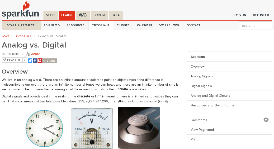
As always, my background in litterature did not help me as much as I hoped, so I had to study again the basics. If you don't know what's the difference between a digital sensor and an analog one, this page will be pretty helpful. Both the analog and digital one are explained very well, and there are some useful links that explains everything about circuits, boards and electricity. Those things may sound obvious for the most part of the FabAcademy's students, but if your university backround is close to mine it will be a good reading.
For everything related to this argument I always take a look at Electronics for Dummies, where I can find almost anything explained.
Light sensor
For the analog sensor, I decided to do a light sensor.
In this assignment
page there's almost everything I needed to do my board. As I saw the components
that I needed for my board I opened Eagle and I started to draw it.
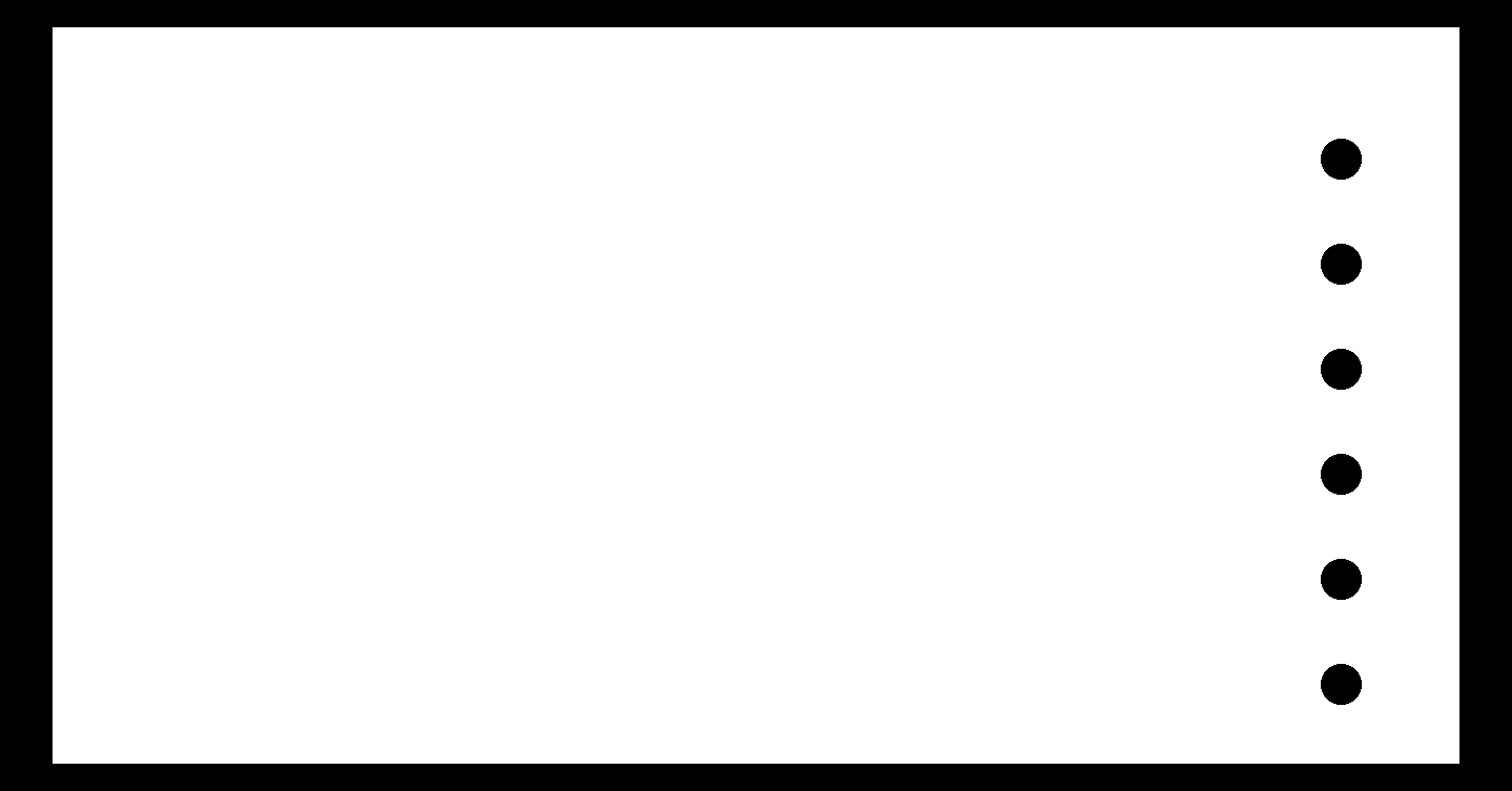
As you can see:
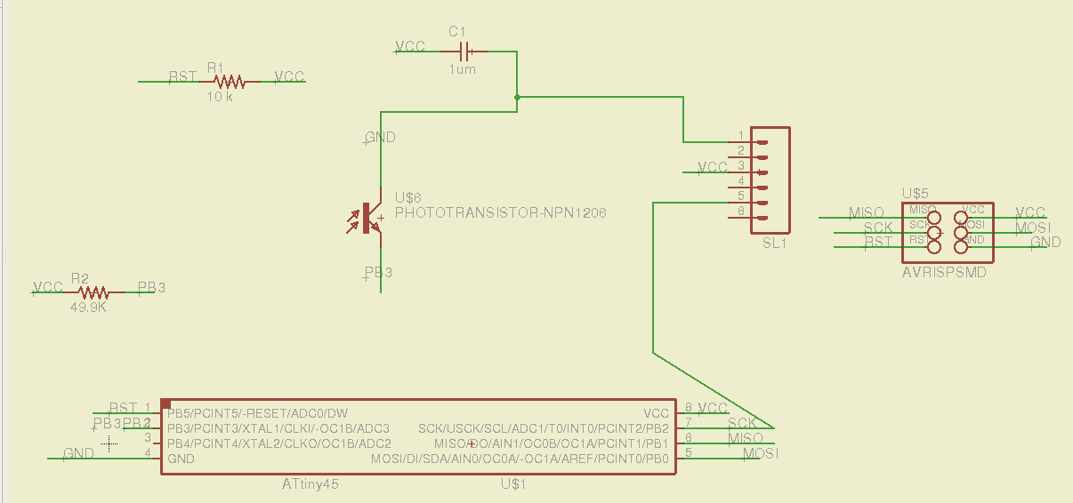
It took me some times to use again Eagle. I've forgotten the most part of what
I did during Electronic's design week, so the first day basically I just used
Eagle and checked my documentation. Anyway, this time I did not do most of the
mistakes I did the first time, and I felt releaved for it. Once I've finished
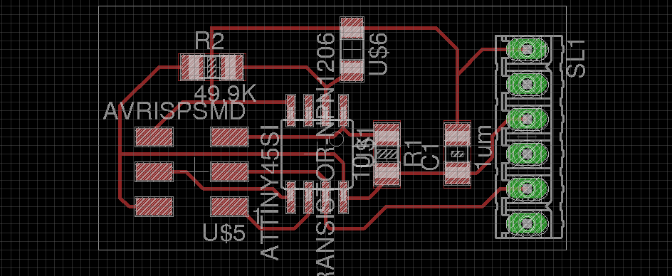
I exported the image as .png:
As I did during Electronic's design week, I used Gimp in order to adjust
the size and to create the cutting file. The most important thing to remember is
to adjust the etching and the cutting image at the same time, or it will be create a lot of trouble.
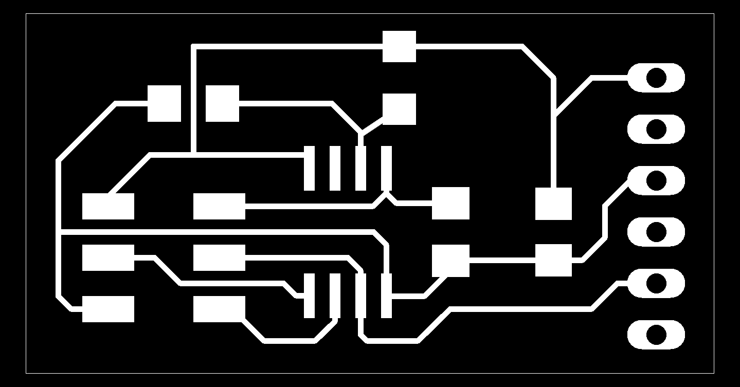
When the .png were ready I generated the .rml files via Fabmodules and I milled it with the Roland:
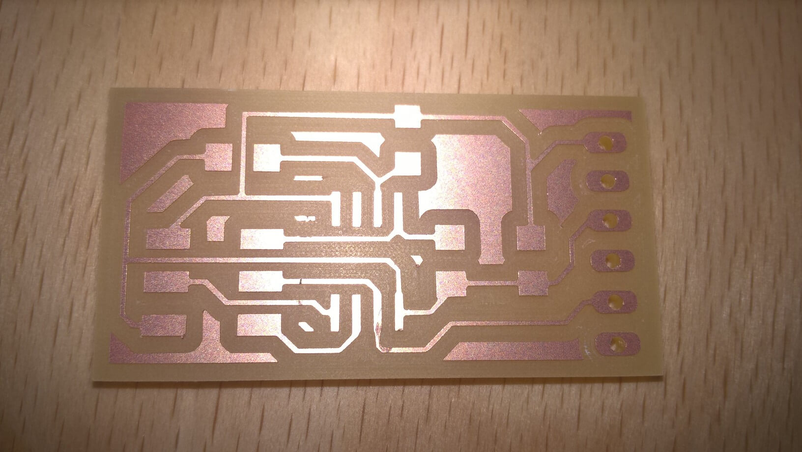
Everything went well, so I proceeded to solder the components on it:
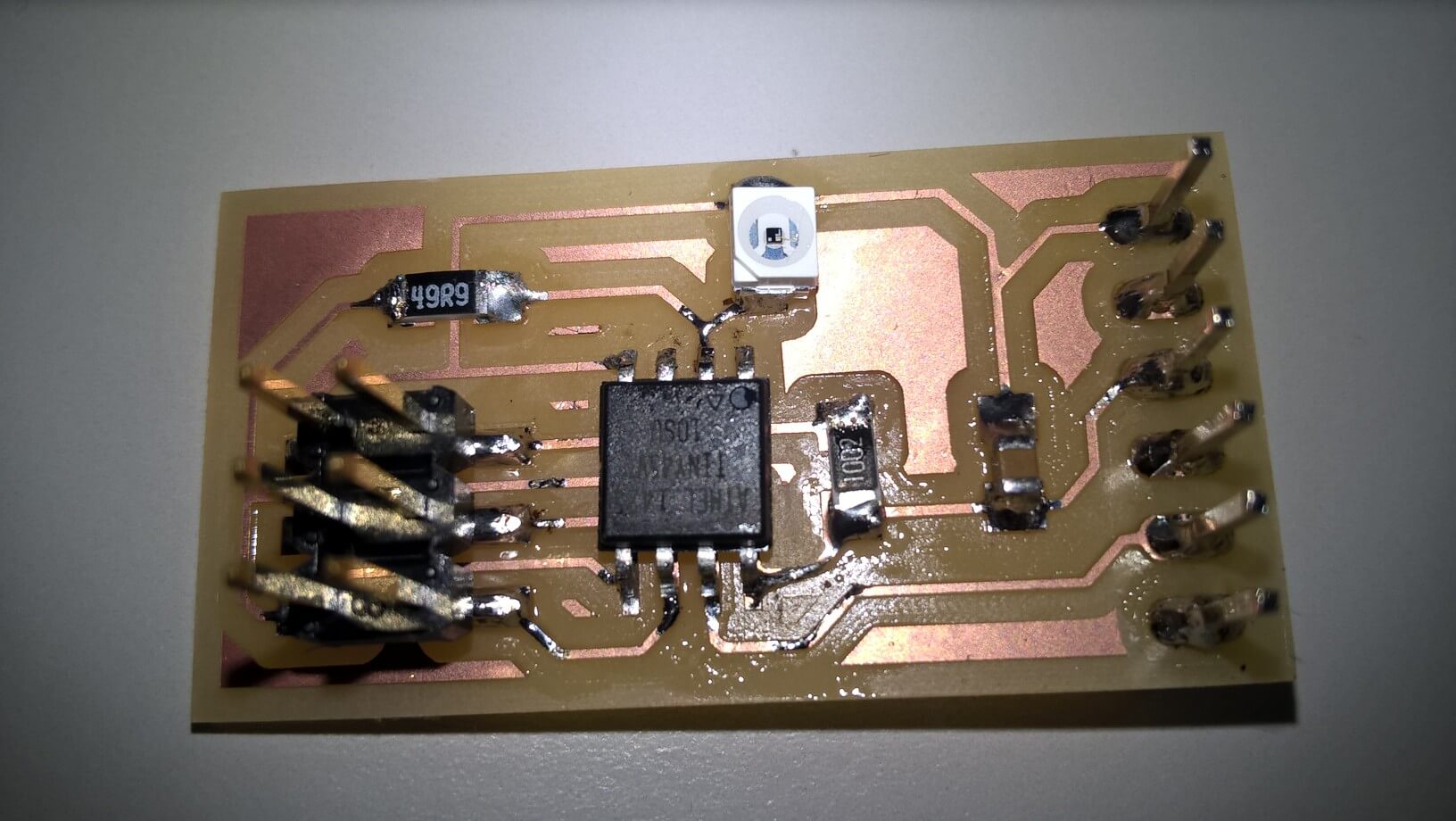
I checked with the multimeter the connections, everything looked ok, so I went for
the programming part.
I downloaded the .py file from fabacademy's page, I fused the board and I tried
to star the python program, but it didn't work. That because I didn't install a
program called "python-tk". Ubuntu users can download it just typing
Button
After the first board I tried to do another one. First I tried to do a board
with a microphone. The idea was to have a digital signal. Anyway, I tried a lot
but in the end I was not able to finish it because we missed a proper component.
Because of this I decided to do a board with a button. I redisegned the board
with Eagle, and since there was a free pin on the Attiny45 I added a Led. My
plan was to test the button response with a python script, and then to use the
attiny45 datasheet to connect the led as output of the button.
Here you can see the eagle files:
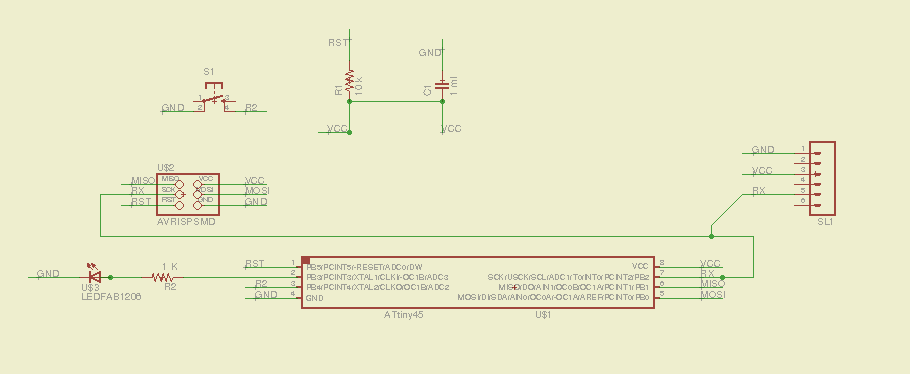
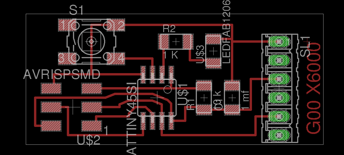
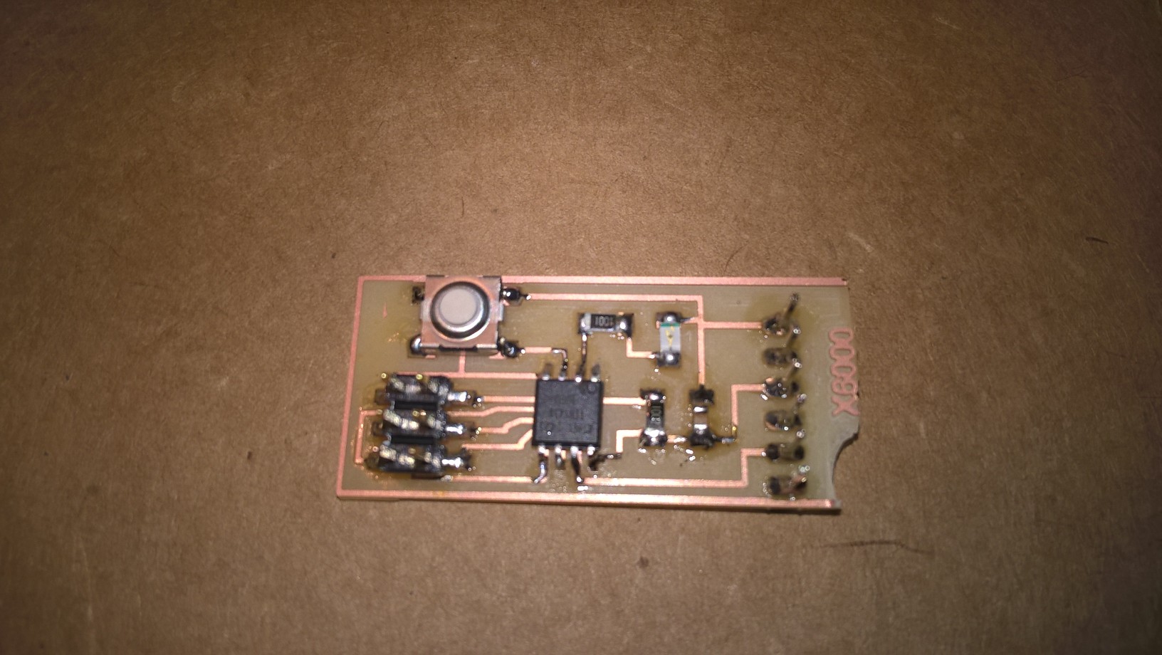
Once I milled it with Roland, I proceeded to solder it, and here you can see the
result. I had a problem, because in the middle of the cutting, the board has lost
the grip and it has started to spin. I finished to cut by hands, that's why it's
so broken, but since the traces where fine I decided to try to use it anyway:
Once the board was ready I proceded to program it:
And then I tested it, I read the input file using minicom:
Sound sensor
I wanted to do a sound sensor because it looked a nice thing to me. First I tried
to do a digital one, but since we didn't have a digital microphone, I tried, studying the
data sheet, to find a solution.
The main problem was that we had a different digital microphone, and in order to
solder that one on this board, I should have changed a lot of things on the schematic,
and it was a little bit out of my league.
Since it was impossible to me to fix it, I went for this one.
Basically, I did what I did for the other boards I made during this week.
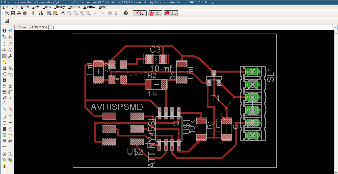
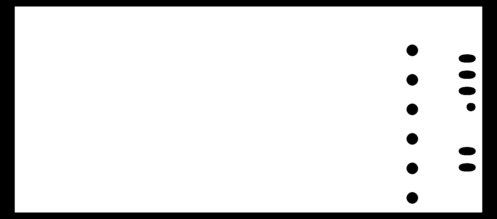
These are the files from Eagle:
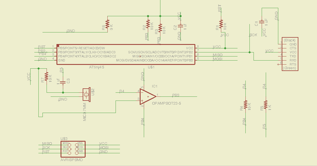
This is the schematic:

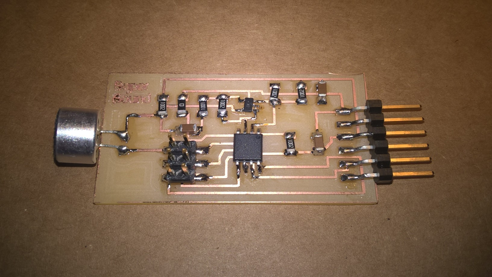
Once the file was ready, I milled the board with the Roland, and I proceeded to
solder it. As you can see, this is the final result:
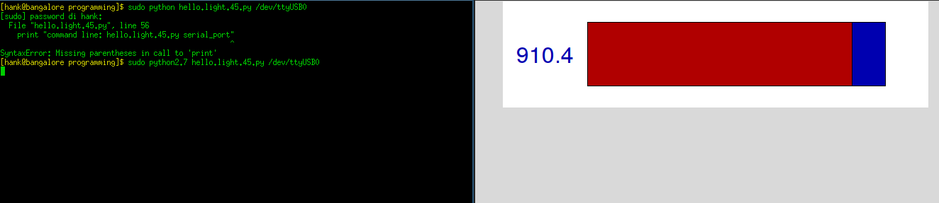
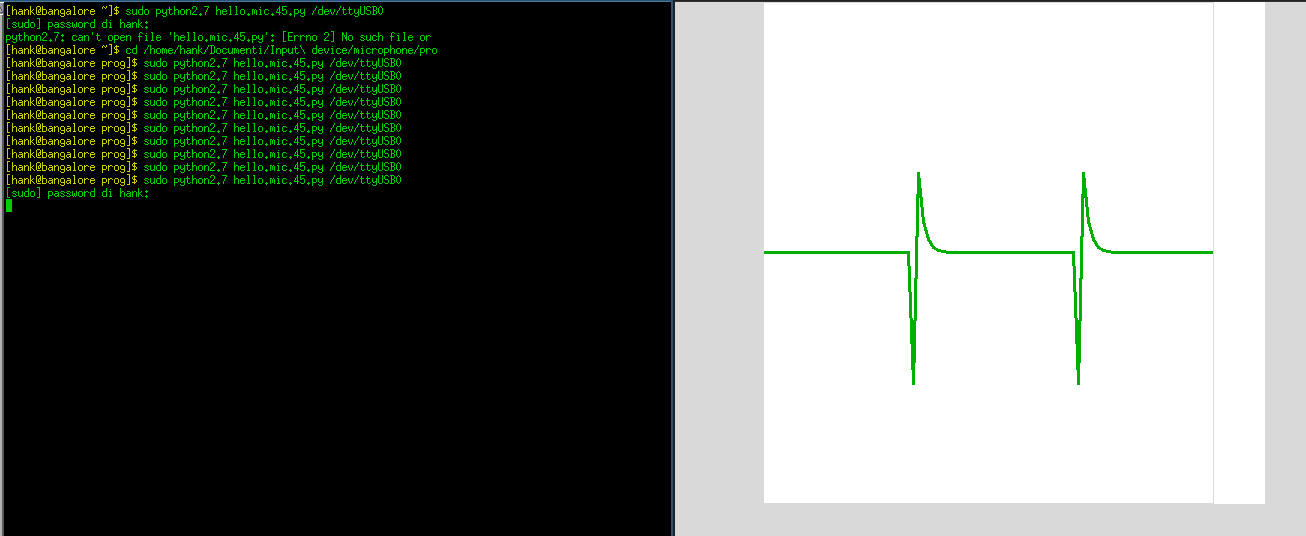
In order to finish it, I fused it and then I launched the python program to use it.
The first time I used it, the graphic was pretty messed up, so i tried to change some
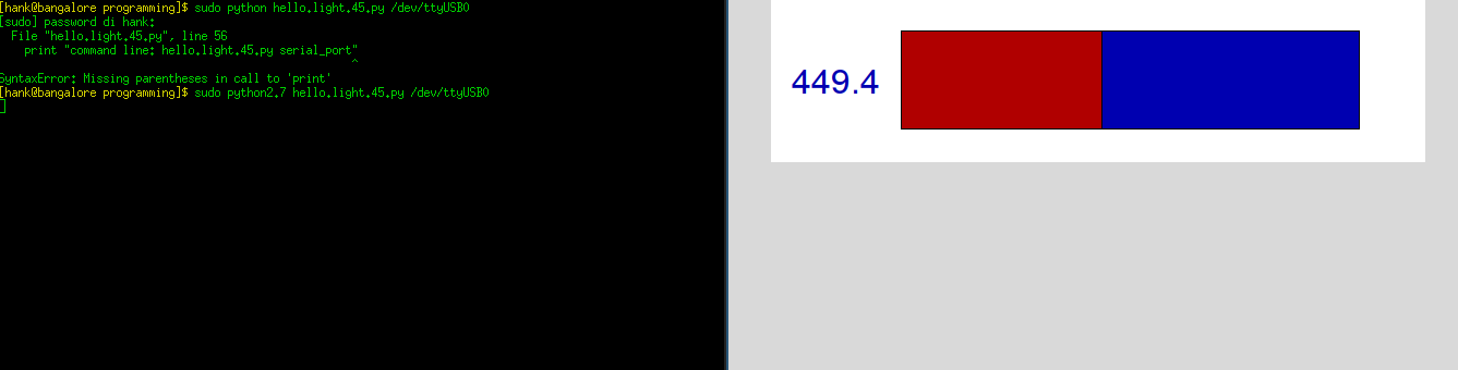
values of the python script:
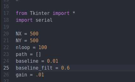
Changing these values I had a better read of the sound, here's the result:
Conclusions
This assignment was much more relaxing than the machine's one. I used again Eagle, I soldered a lot and I used python, it was useful in order to fix a lot of things I learned during the past weeks.
Download
Light sensor board
Etching board .png
Cutting board .png
Eagle board file
Eagle schematic
Button sensor board
Etching board .png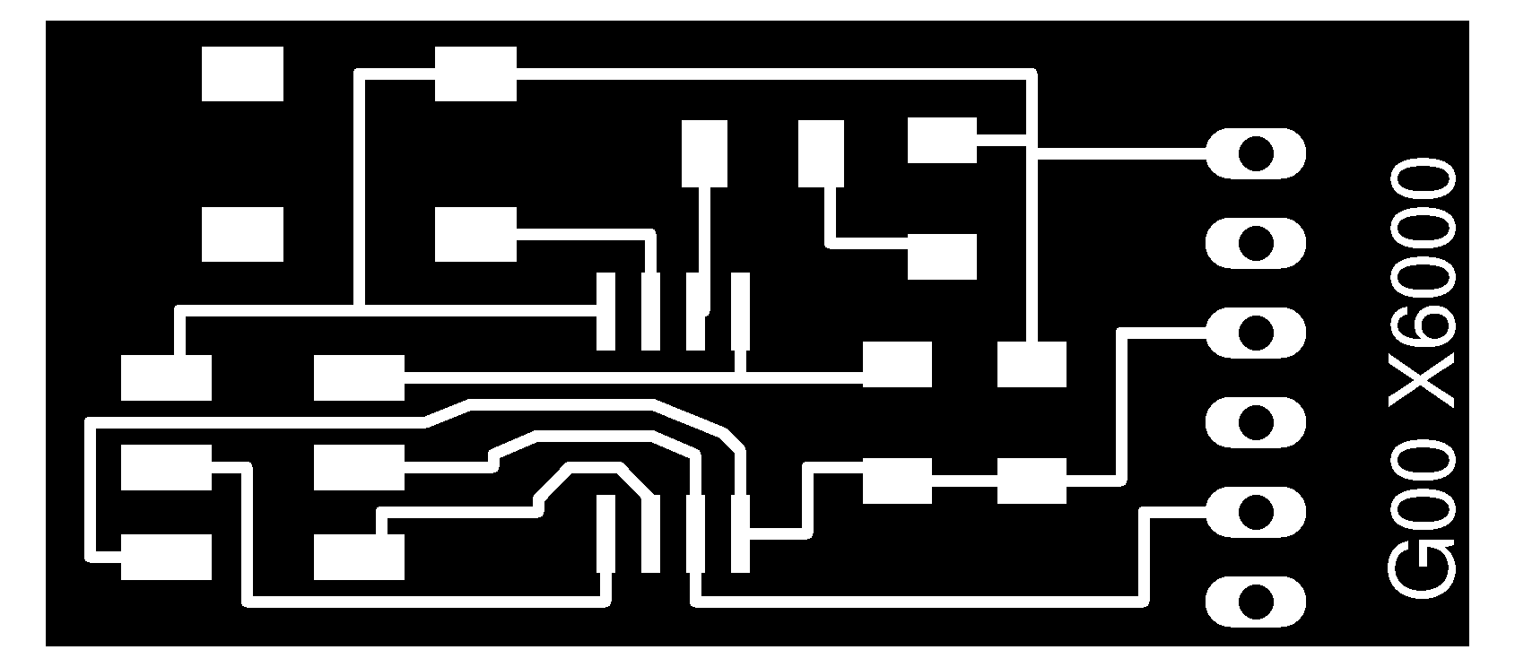
Cutting board .png
Eagle board file
Eagle schematic
Cap sense board
Etching board .png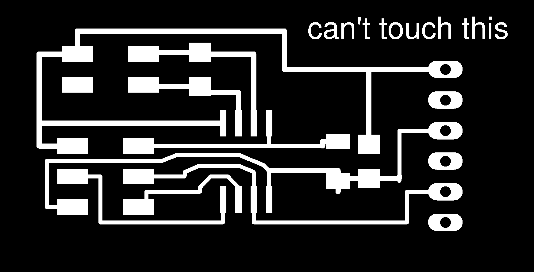
Cutting board .png
Eagle board file
Eagle schematic
Sound board
Etching board .png
Cutting board .png
Eagle board file
Eagle schematic

This work is licensed under a Creative Commons Attribution-ShareAlike 4.0 International License.